Τετάρτη 29 Ιουνίου 2016

Dual motor airplane , different output - fix

Hello friends.

I have setup a dual engine electric airplane, CL 415 , canadair - waterbomber.

Here's the setup

2x 1000kV motors 2212
2x 80A ESC
2x 10x4.5 propellers

4x common 9g servos
3S 4000mAh battery


Here's the problem:
As I start to increase throttle from 0%  the one motor spins while the other does not.
At around 30% of throttle the other motor starts to spin
so there is 30% throttle  difference between the two motors which creates huge horizontal torque  making the airplane really difficult to fly.

I thought that I could use a  flight controller  such as  CC3D but after  looking into it's software  I realized that it does not support 2 engine airplanes, or at least unmatched twin engine's.

So I star wondering around and reading how things work, and found a solution.
I had to calibrate the ESC's

I used a Y-cable, at the channel #3 of the receiver, powered on the esc's while having full throttle at the transmitter , and after motors started beeping, i decreased throttle to Zero - then full throttle.

ESCs Calibrated - Problem solved   (initially I thought that these ESC's  were hardcoded and could not get calibrated , but i was wrong)

:D

Interfacing Lcd i2c with arduino 0X3F for board with MH marking

Interfacing Lcd  i2c  with arduino  0X3F  for board  with MH marking


While there are many identical  i2c converter modules out there,  not all have the same circuitry, which leads to frustration after using LCDi2c library only to find out that there is no lcd output.

After some research I  found the new i2c  library  which  you can download and add on the arduino library folder


test  ok

for more about this  library check here
https://arduino-info.wikispaces.com/LCD-Blue-I2C

Τρίτη 28 Ιουνίου 2016

DIY RC Deep-V Fishing boat 60cm

Hello Friends.

After another friend's request,  I start building a deep v  boat, intended as bait boat.

The first designed version was 180cm, but that was really too much and inconvenient to carry around as a "fishing utility". That also pushed 3 x  times the limits of my cnc router which has max 60cm operating range, so redesigned it to fit a lot of parameters.


(The blueprint)


In this boat I will install a telemetry system, based on my original telemetry development  ,
slightly modified from the original version which will feed data to the fisher-pilot :
  • Distance from home(or shore or starting point or set point)
  • Speed (Kmph/kts)
  • Water Temperature c/f
  • Ambient temperature (external) c/f
  • Internal Temperature c/f
  • ESC Temperature  c/f
  • Battery Voltage (battery of ship)

 After the design I followed  the conversion protocol in order to generate the GCode.
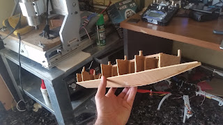
Then I started cutting a 3mm ply wood and made this


Then had to glue these pieces together .

 And after gluing, more gluing followed which gave a boat shape to the wood parts


And again, more gluing 


The creation goes on. For now, glue has to dry out

OK, a new update 13/7/2016

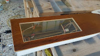
After 10 days and lots of painting and drying and sanding, i guess its time for the sea ! 


Here is the third test


Τρίτη 14 Ιουνίου 2016

Long range radio telemetry for RC plane/drone/boat/car

Hello friends

I built a telemetry pair for a friend. An idea I used to have for a really long time, but I had lack of interest to do it only for myself.

The purpose of this project is to have on the field a lightweight handy standalone system which works with only a button instead of carrying a laptop and all its modules.

All the system is based on arduino and NRF24L01 Transceiver module. (on the very begginings I had problems with the code on the atmega328 mcu on the TX side and so I was forced to use atmega2560 for TX which was very heavy for that application. After the code optimized runs fine on the atmega328)

The maximum range that I have reach using NRF24L01 LNA/PA/SMA is 2kM LOS with the stock antennas .

The data that is transmitted at this point :
  • Speed (km/h)
  • Altitude(m)
  • Temperature (internal) (Celsius)
  • Battery Voltage of the battery of the plane (up to 4s battery) . 
  • ****Added in the new version (28/6/16)****
  • Distance from home
  • Coordinates
  • External Temperature
  • Running Time
  • Set here as Home function 

Speed is determined by Ublox neo-6m GPS module
Altimeter and temperature is determined by BMP180 barometric sensor
I added a toggle switch which resets the altitude before flight (or in flight).

There is alarm for STALL, OVERSPEED , LOW BATTERY, OVERHEAT and Lost Signal , which lights a LED and sounds a tone on buzzer.
Stall and overspeed set values are hardcoded variables which can be changed in the code. (Maybe in the future versions will add potentiometer to adjust the stall/over speeds)

Panels for the ground station are cut on CNC Router and then put carbon fiber - look coating.

I could use a 2004 display instead of 2x 1602 , but i did use all components i had on hand.
I could also use apm 3dr and a laptop and have lots of telemetry data, ready to go! But hey, thats what I had on hand and its handy to carry around and it would cost less than $50 for a new pair.


Here is the (Second) field test, on a phoenix 1600


Below are some pictures of the telemetry system


This is the transmitter module.Removing tape,wood,glue and shorting the length of cables it can easily drop to less than 50gr. 


One thought was to install instruments (of which the needle has limited degrees rotation like airspeed, controlled by servo, or unlimited rotation actuated by a small stepper motor) but for a first panel is much invest of time.


Currently I am developing the next version of it, which in addition to previous data will also display:

  • distance from home    dev OK(28/6/16)
  • plane coordinates        dev OK(28/6/16)
  • external temperature   dev OK(28/6/16)
  • system running time    dev OK(28/6/16)

*The home coordinates are hardcoded but will implement a button function to set-here as home
>>>> Function implemented OK (28/6/16) 


Other data that I am interested in adding in the future are
engine RPM (here I need some help on how to measure)
Current consumption (mAh) (will probably use the APM power module)
g load
pitch roll position (to be displayed as artificial horizon)
SD card data logger (as Black BOX)
RSSI


Another feature I intend to append is remote control (from the telemetry receiver to the telemetry transmitter on the plane), that will open a hatch to drop parachutes (probably controlled by the operator, not the pilot)


**Update 25/6/16 :  After some consideration, I intend to shrink the whole design to just one 20 x 4 LCD in order to be mounted on  top of  the pilot's RC Transmitter (in case that FPV monitor is not used)
Probably it will be quite convenient  (instead of having another box somewhere nearby).
Will study and post really soon !

**Update 26/6/16:  I made an alternate version to fit the data on the 20x4 LCD.   Sending coordinates and distance (plus all other data)  is overkill for the atmega328, so for now  distance from home is transmitted (instead of coordinates) .


Please share your thoughts regarding this project


(Ok , that's my first blog post ever.
                    I will try to update it and improve all my development, under development !)

Thank you.